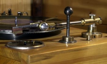
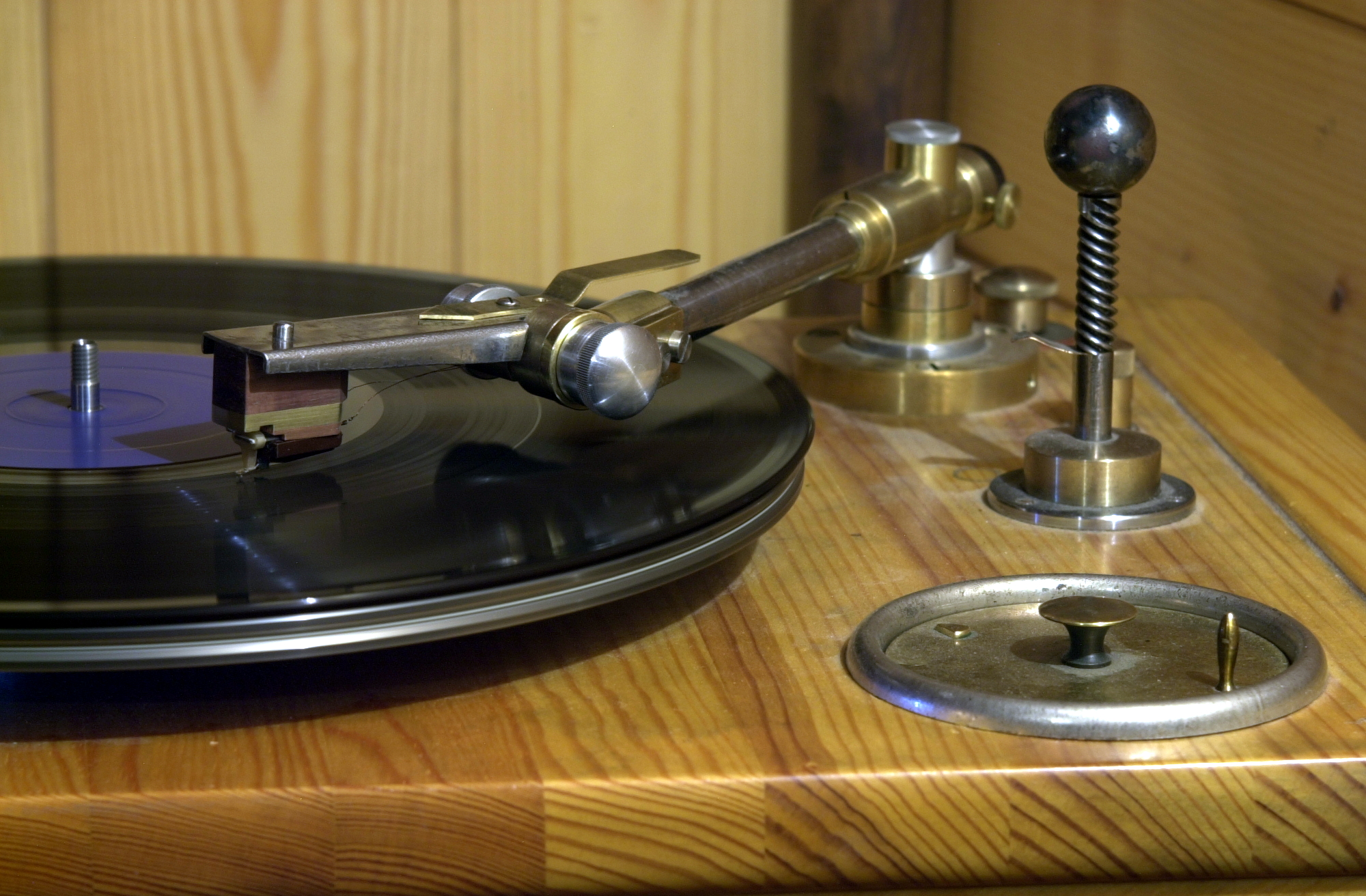
The main difference between the new tonearm and the previous one is a short vertical stroke, which allows you to hold the needle in the groove of the warped plate with less noise and overload. During the operation of the Bend Spring Tonearm, it turned out that there were such warped plates at 78 revolutions exist that even the spring tonearm can not hold the needle in the groove. There is no question of playing such discs with a tonearm with a counterweight.
For the sake of the necessary short vertical stroke I had to go to the complication of the tone arm design – to make the units of vertical and horizontal rotation on ball bearings. In the previous version, the vertical stroke was gracefully made on a bent spring and a pair of blade supports. In the new version, either precise milling work would be required in order to place the bent spring at the end of the tonearm, or a design would have to be made from a large number of parts. Both options, for various reasons, would have a bad effect on theclarity of the sound of the tonearm. In this situation, it would be possible to use a spiral tension spring, but I, like last time, needed a design without dampers; the only acceptable option in this case is a flat spring. That’s what I decided to use in the new project.
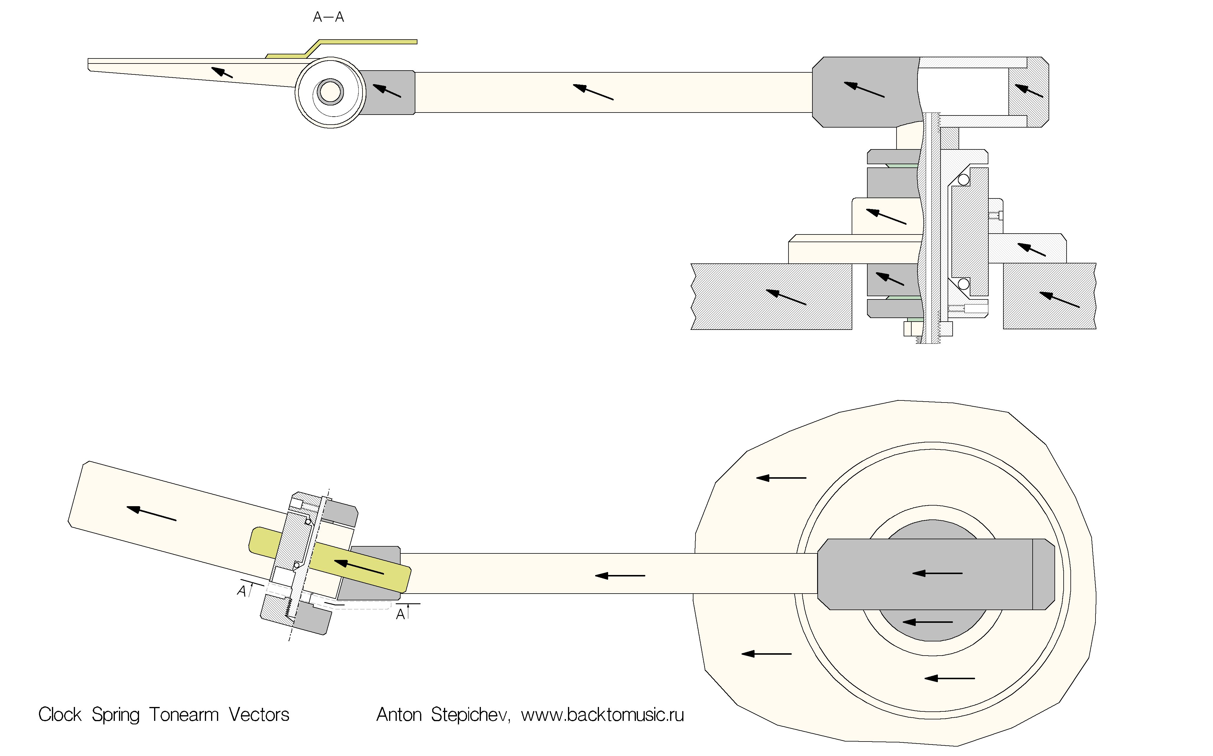
The most difficult current task was to maintain the high < em>clarity of the sound inherent in the first, structurally simpler version of the tonearm. For this purpose, the selection of materials was carried out carefully, in several stages; many units and parts had bee re-tuned and reworked several times, even for the sake of a minimal improvement in the sound, which in a normal situation hardly anyone would pay attention to. The vector orientation scheme of the tonearm parts (Fig. 8) was once again uncompromisingly checked and refined. This approach was primarily necessary because the design contained ball bearings, which in principle cannot be correctly oriented. The most of losses occurs precisely in chaotically directed steel balls, and to compensate for these losses, the parts of the remaining units must have a perfectly neutral coloration and are oriented as accurately as possible relative to each other.
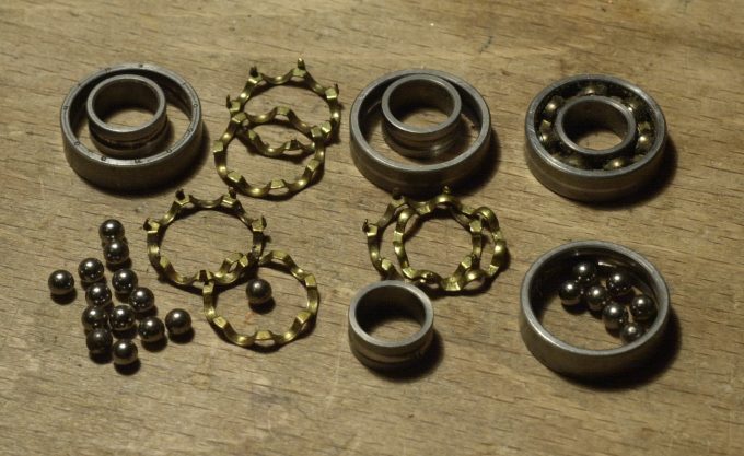
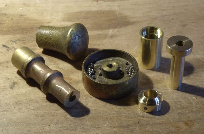
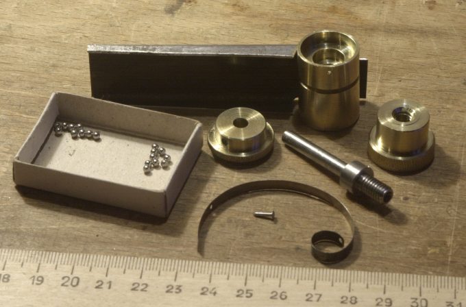
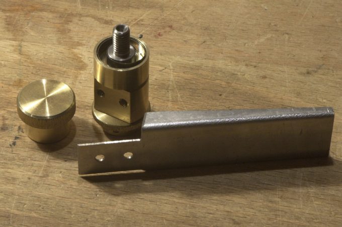
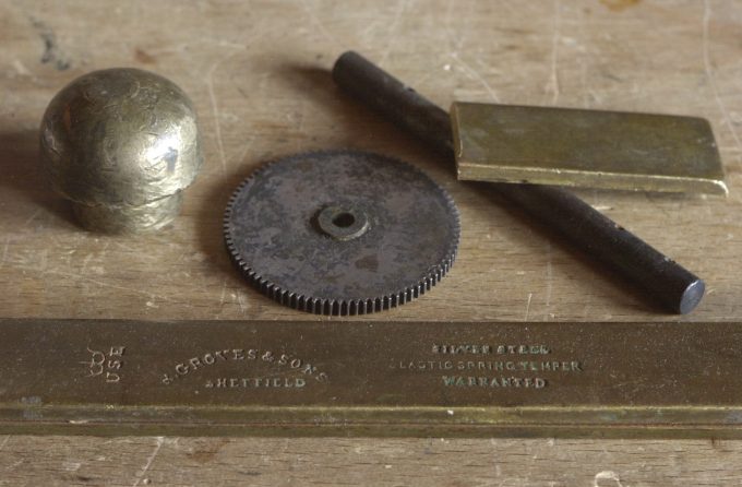
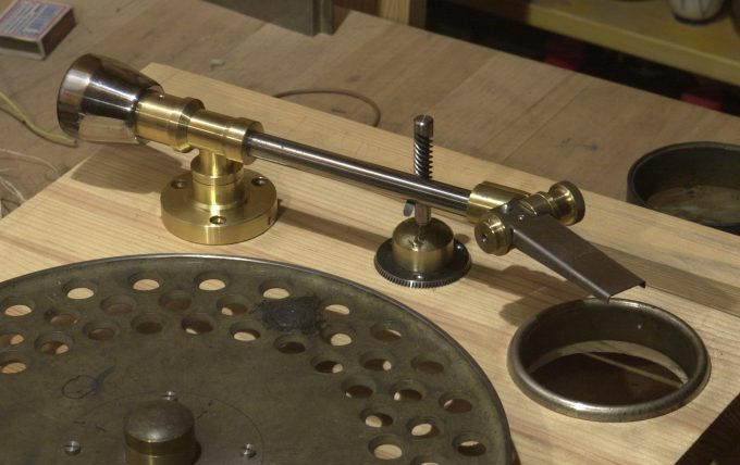
The design of the horizontal axis bearing is borrowed from the Orthophone tonearms of the 1950s, the body material is bronze from old candelabra. The balls were removed from Soviet bearings from the 1950s (FIg.1), the oldest ones I could find. The base of the bearing is made of a bronze wheel from a 19th-century indoor grand piano (Fig. 2 in the center), great sounding material! The tonearm shell is combined with a vertical axis bearing, the design of which is identical to the horizontal axis bearing, except for the smaller size and modifications associated with the mounting of the spring and shell (Fig. 3). In one of the ends of the bearing, a recess is made for installing a flat spring, one end of which is fixed to the bearing axis, and the other end is fixed to the rotating part of the housing (Fig. 4), where a platform for attaching the shell is cut. The tonearm shell is attached to the arm by means of a nut (Fig. 4, left; Fig. 6, right), which is screwed onto a thread cut on the protruding part of the shell bearing axis (Fig. 4, top center). With the help of this nut, the necessary pressure of the head to the plate is also fixed, after it is installed by rotating the opposite end of the bearing axis.
The balancing counterweight of the horizontal axis bearing (Fig. 6, top left) had to be abandoned, with it the tonearm became too inertial in the horizontal plane of rotation. This practically did not reduce the quality of rotation of the unit, balancing of which is mandatory only in the case of using a sliding bearing, as in the previous version of the tonearm; for ball bearings, perfect balancing is generally contraindicated, as it leads to a rattle of the unit.
The tonearm was tested with a homemade piezo cartridge made on the basis of an old Ronette cartridge, from which only half of the lower part of the body with a needle holder and an elastic lever that transmits vibrations from the needle to the piezo plate remained. The upper part of the case was made of brass, because after the first fitting, it turned out that it is necessary to increase the weight of the shell tip by 8-10 grams. The head wasattached to the shell through a wooden gasket. The assembly structure is shown in Fig. 8.
In Fig. 1, the arrows show the directions of the Vectors of the tonearm parts: the vector of each of its parts should, as far as possible, be directed as accurately as possible from the bottom up and from the base to the shell, thus duplicating the direction of the earth wire. The most problematic thing is to correctly orient the threaded connections, where it is impossible to predict the direction of the transverse projection of the Vector of the screwed part. To correct the position of the part after its final tightening, the error angle is determined (using probes or tactile method), then from the end of the nut or from the support part of the bolt (where it is more convenient), a part of the metal equal to the thread pitch minus the error angle divided by 360 is lathed off.
The spring is oriented according to the rules of the spatial direction of winding coils of the inductors in all three projections (longitudinal, radial and tangential) see gimlet rule. For an accurate vector orientation, not every factory spring is suitable. Only two vector projections out of three can be guaranteed (in length and in thickness), the orientation in width is chanced in fifty percent of cases. Such incorrect springs will be formally correct if they are not twisted according to the rule of the gimlet, but in both “partially correct” versions, the loss of Clarity of the sound of the unit will be noticeable. So for the perfect sound of the tonearm, you need to find a blank that is suitable not only for its physical properties (size, flexibility, etc.), but also with the direction of its Vector that is initially suitable for this case.

