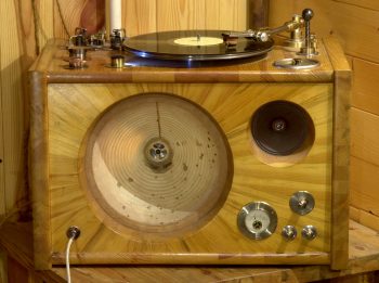
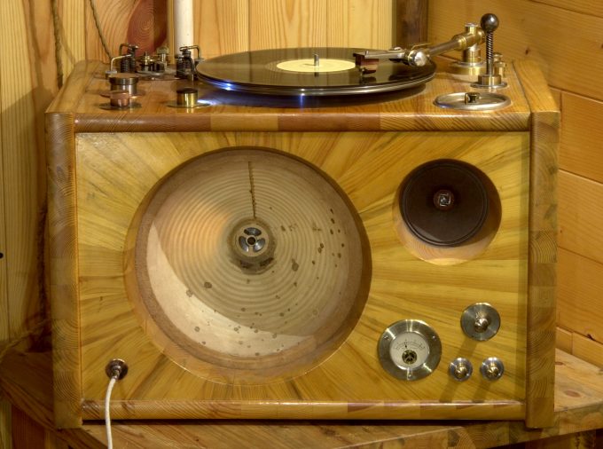
Due to various difficulties, the new analog audio project took almost two years, during which time some ideas became obsolete. I had to deliberatly reconcile with some secondary shortcomings but the most important and difficult moments had to be repeatedly reworked. The project was completed by a willful decision not to touch or improve anything else. At the end an Energy horn and record player hybrid materialized – the younger brother of Testing Audio System called "Energophone". Amen.
Cabinet
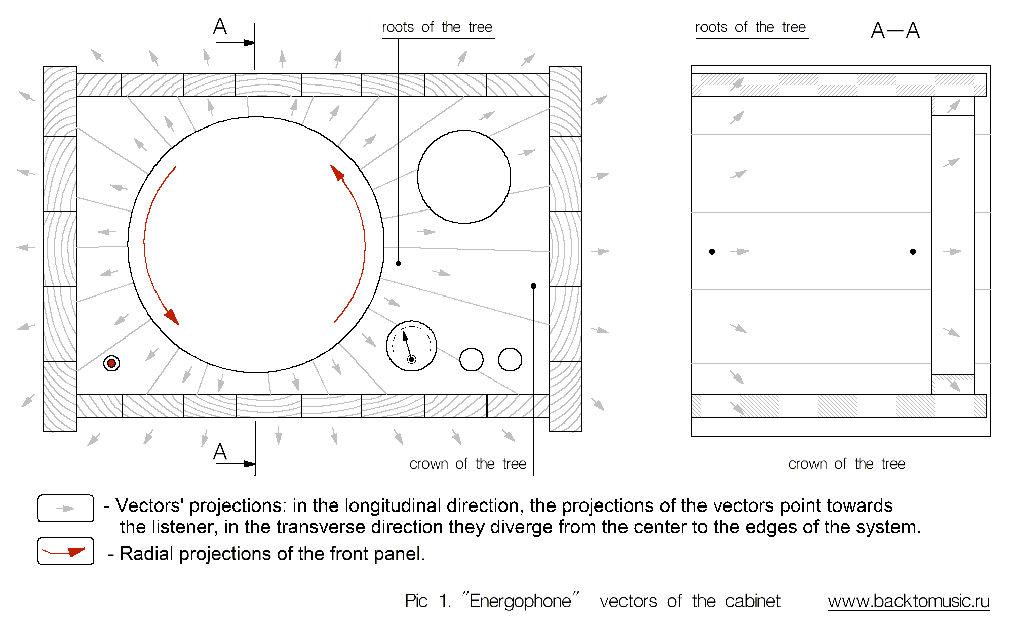
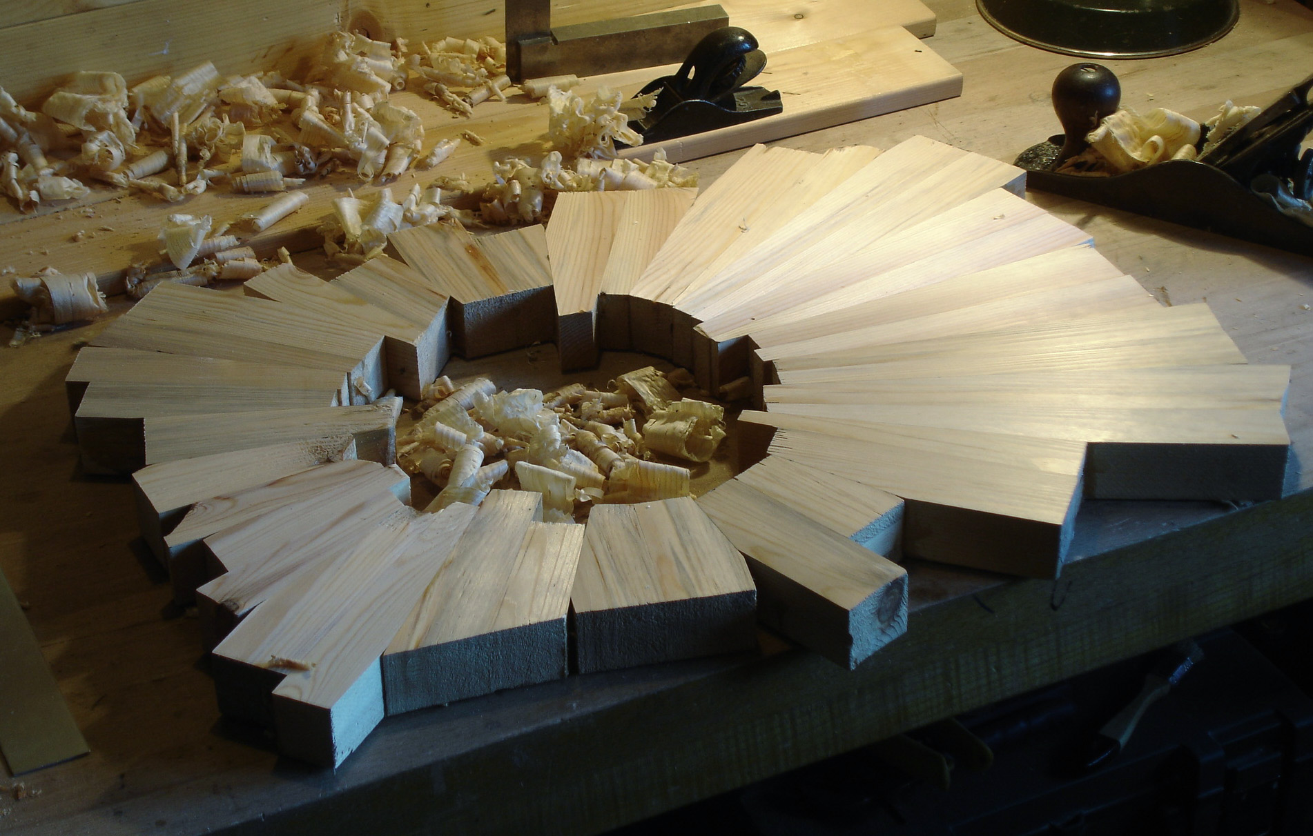
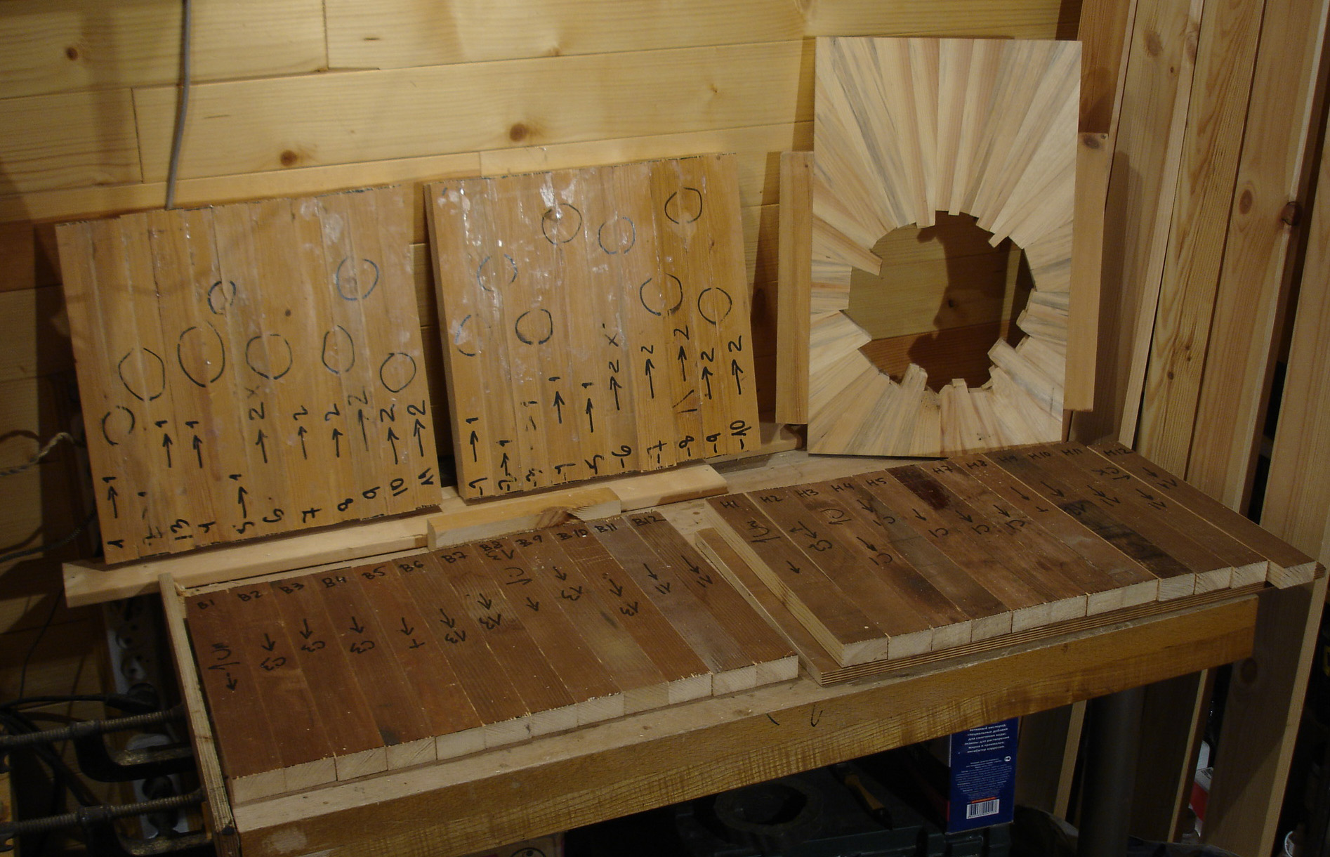
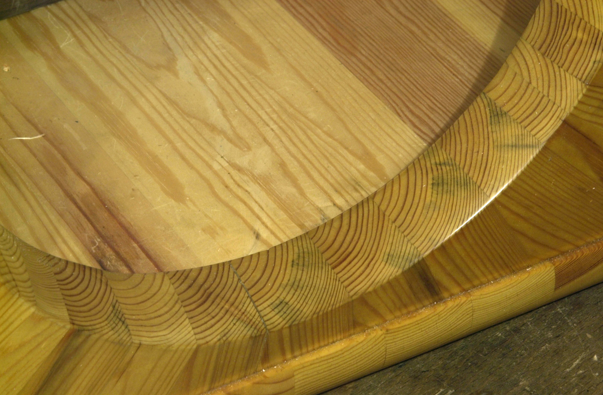
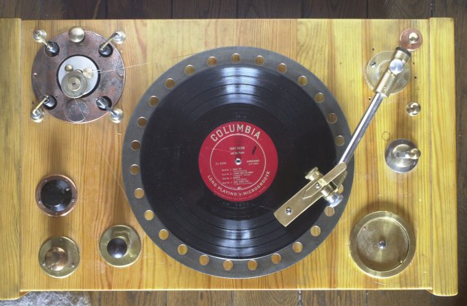
The manufacture of the cabinet and its features are described in the article "Energy Horn" (EH). The front panel is slightly different from the EH panel – it is made up of planks with oblique layers so that when the sound spreads in the direction of a listener there was a clockwise rotation of the resulting vector (see pic. 1 and 4). The body of the tract is covered with homemade amber varnish.
Woofer
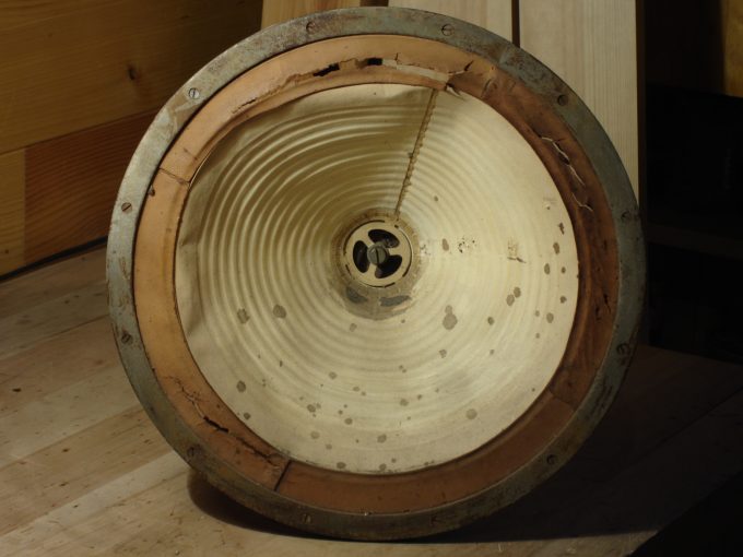
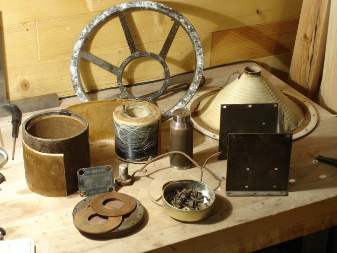
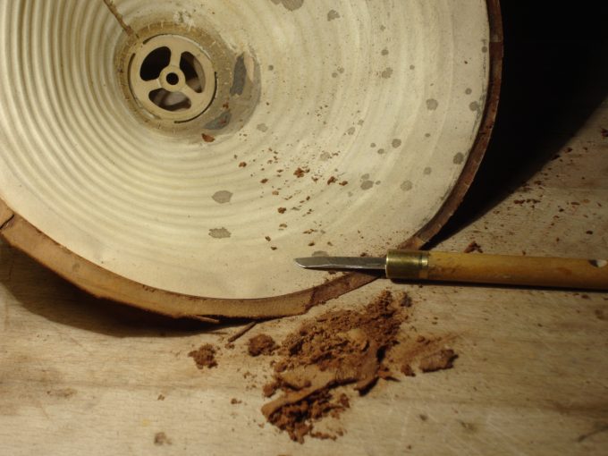
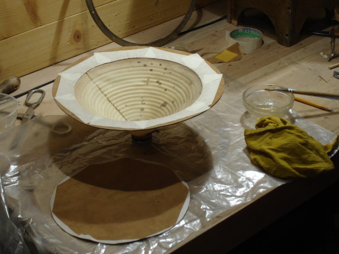
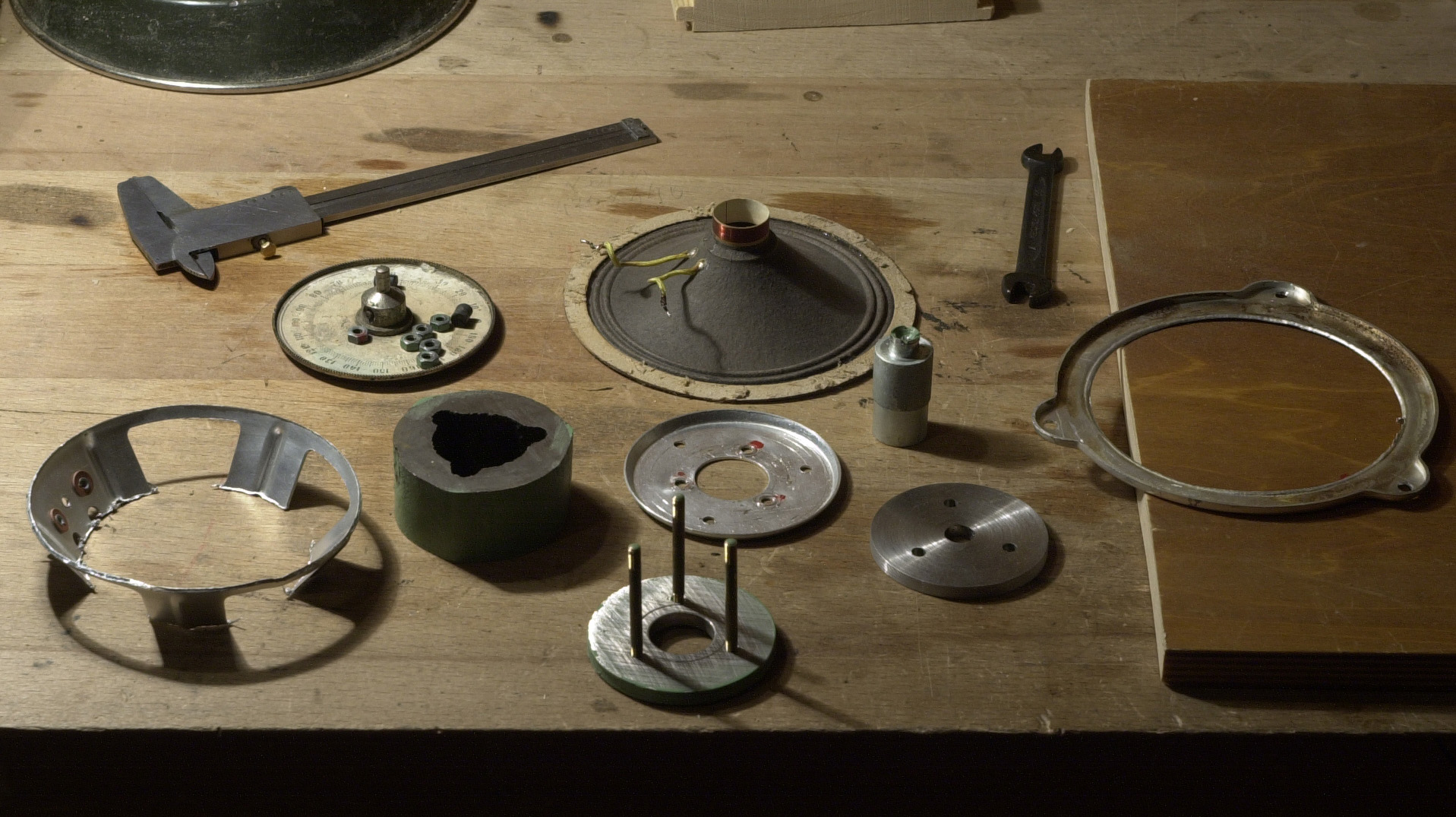
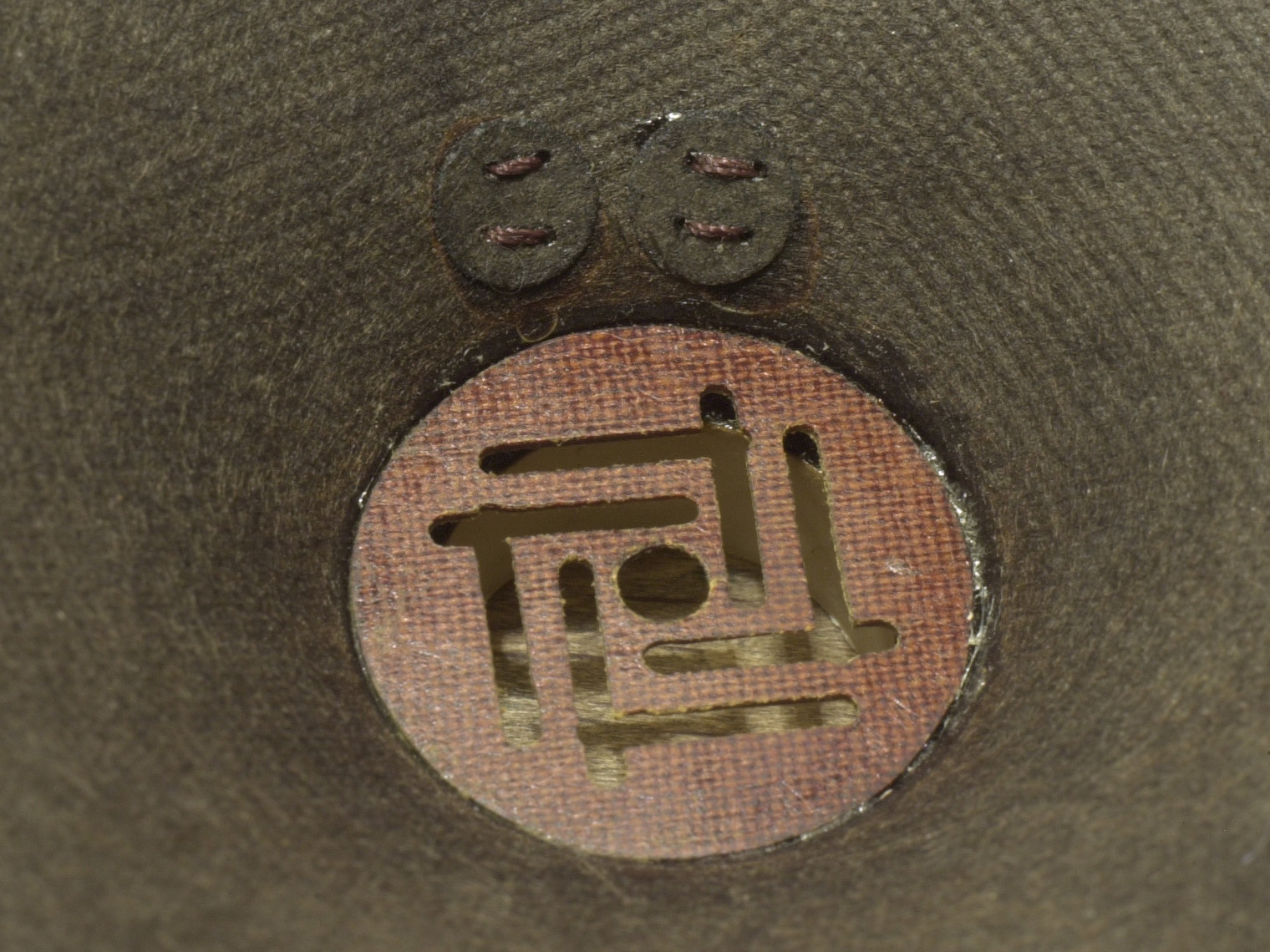
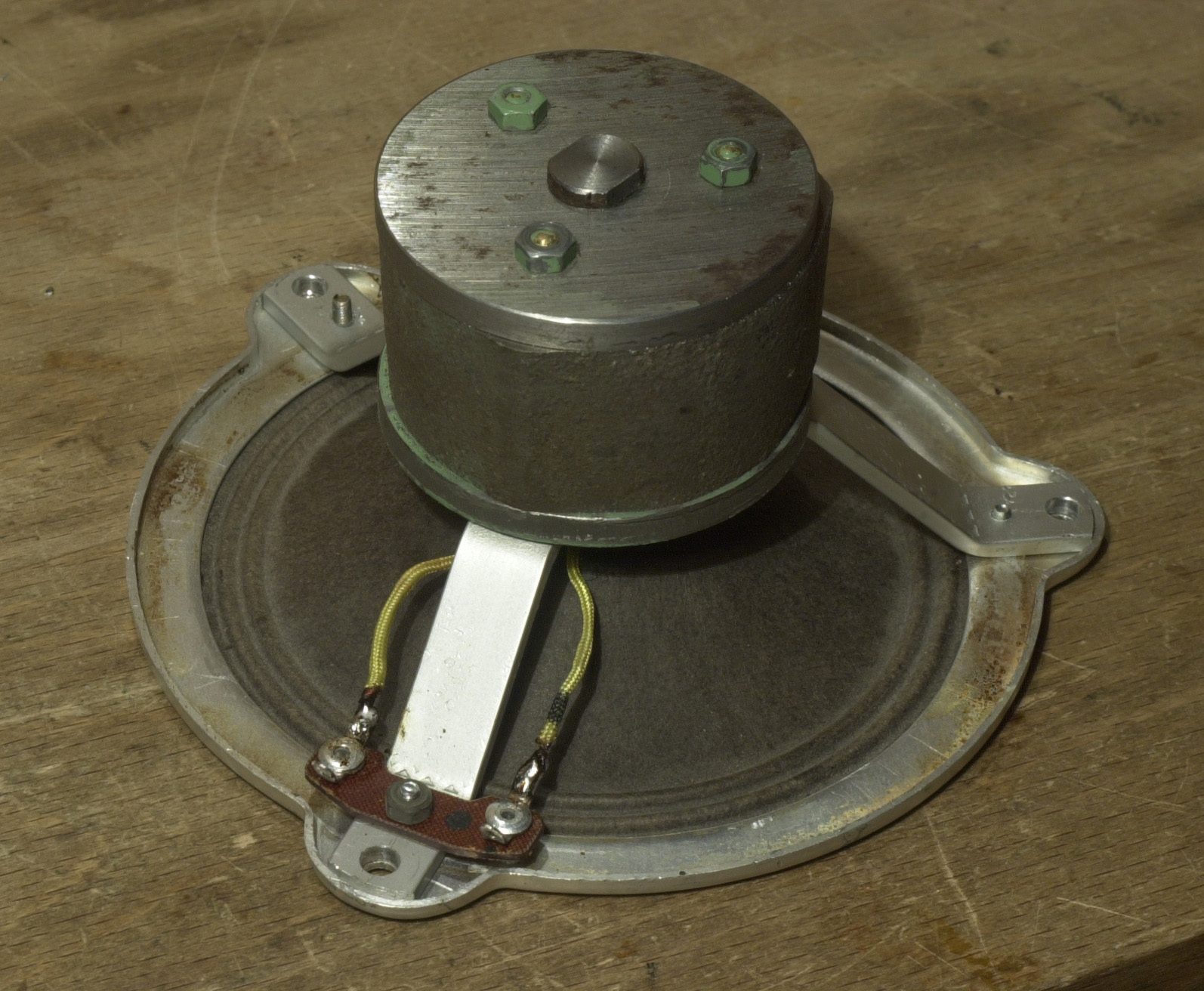
The British Thomson-Houston loudspeaker, made in the late 1920s, was restored for the project. The diffuser is a rolled-up corrugated sheet of paper. The diameter of the basket is 325 mm, the diameter of the paper cone is 250 mm. Voice coil 12 Om, 4 layers 5 mm wide, wire diameter 0.18 mm, coil diameter 40 mm. Field coil – 4 kOM, 30,000 (!) turns of 0.24 mm wire.
Unfortunately, the loudspeaker had two parts that could not be properly orientated: the basket and the body of the field coil. The basket could only be made new, and the body could be disassembled and turned over, but this required a large press, work on a big lathe machine, and a large billet of good-sounding old iron. There were no one of this at the moment and the uncompromising version of the speaker was postponed until better times.
Tweeter
Exactly the same head as in the Energy Horn was used. The speaker's basket and spider were both directed in the opposite direction and they had to be replaced with homemade ones. It was also necessary to replace the flexible wire connections and terminals, rewind of the sound coil was not required.
Motor
It took five times longer than planned to work with the engine and drive mechanism. At first, quite reluctantly, I had to stop using the unique engine that was used in the Testing Audio System (TA). The motor was seriously damaged and in addition it was a brushed one. The contact pads of the rotor were badly worn and despite all efforts to lathe and polish the surface, the brushes often began to spark and interfere with the sensitive cascades of amplification. The interference disappeared as I added RC filter on power supply, but when it came to listening tests it was clear that filters worsened the sound of the antique motor, bringing it closer to the less interesting sound of the 1930s engines. After several comparative tests and an assessment of the sound quality of the available engines, it was decided to use an asynchronous motor with a short-circuited rotor from a 1920s American electric gramophone.
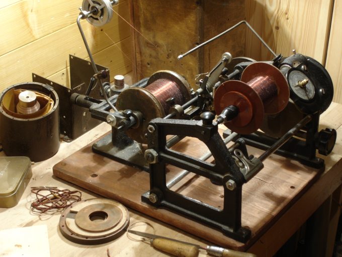
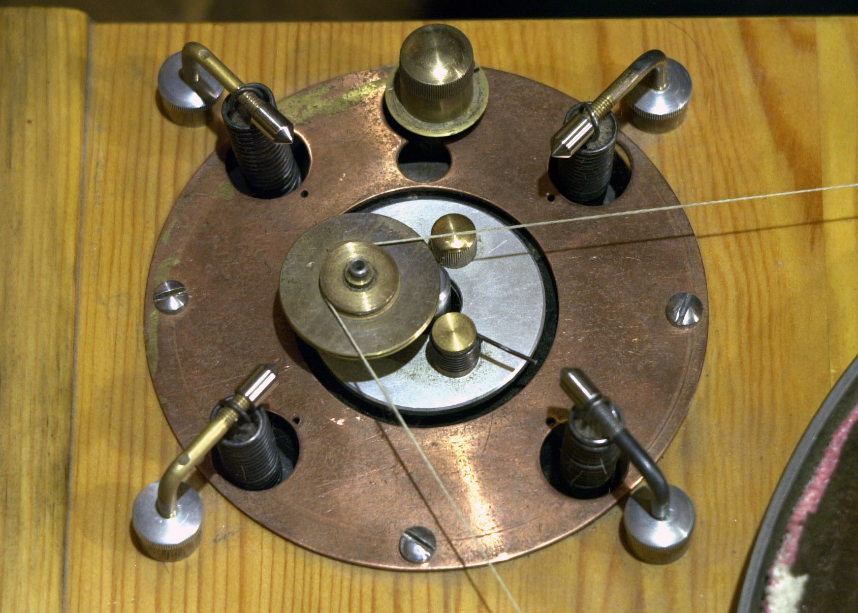
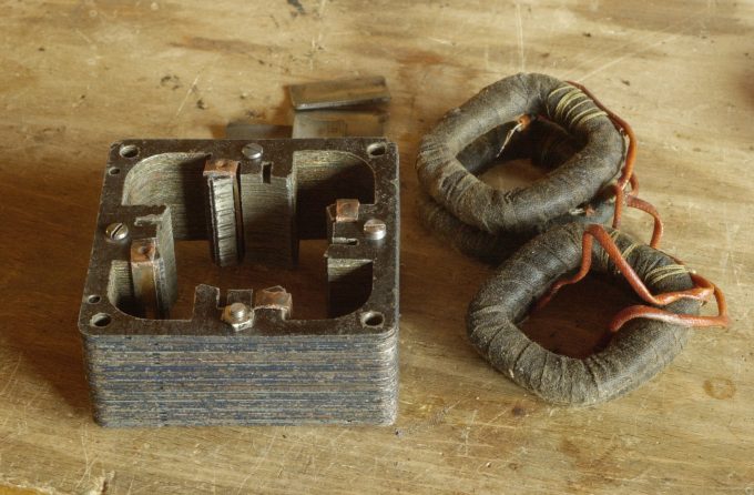
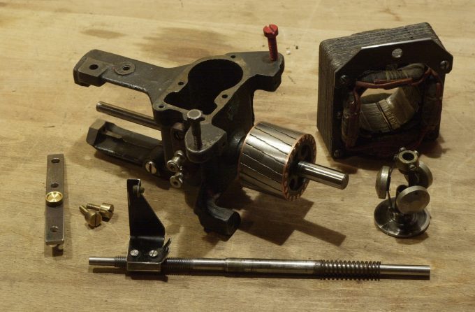
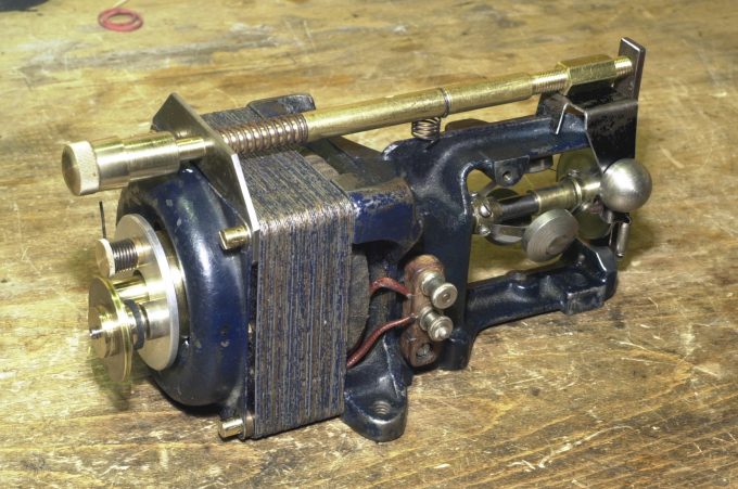
The motor of the US depression period was not assembled perfectly, the rotor is poorly balanced and pressed on the axis unevenly, roughly machined on lathe tool right up the top. The holes for the bearings in the housing are not drilled coaxially, which is why the replacement of worn bearings has turned into another problem. The engine was completely disassembled except for the rotor: it was impossible to pull out long, deformed copper rivets that tightened the plates of the rotor magnetic core. All other components, including the stator plates, were connected as far as possible co-directionally - "from the bottom up" relative to the future location of the motor in the cabinet. The stator windings were rewinded, a homemade speed control drive was assembled with a regulator located on top of the cabinet. The working position of the engine was changed to vertical, in this regard, it was necessary to make an additional bearing lubrication system. After assembling the engine, it turned out that the engine was rotating in the wrong direction. I had to invent a mechanism to change the direction of rotation as well as a three speed reductor and belt tension adjuster. After several unsuccessful attempts, the problem was finally solved both by sound and technically.
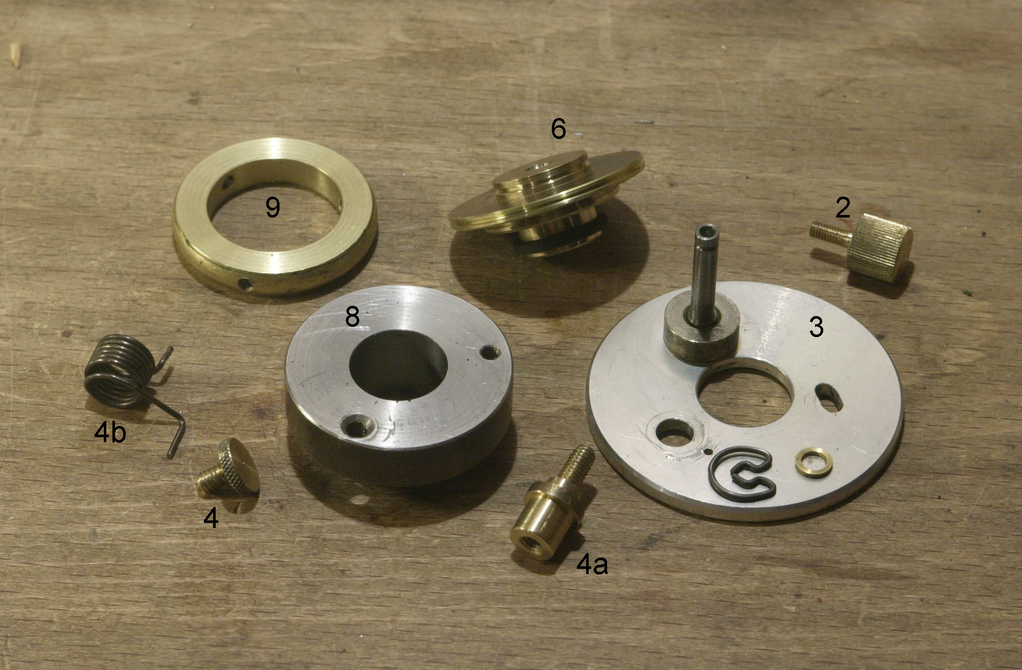
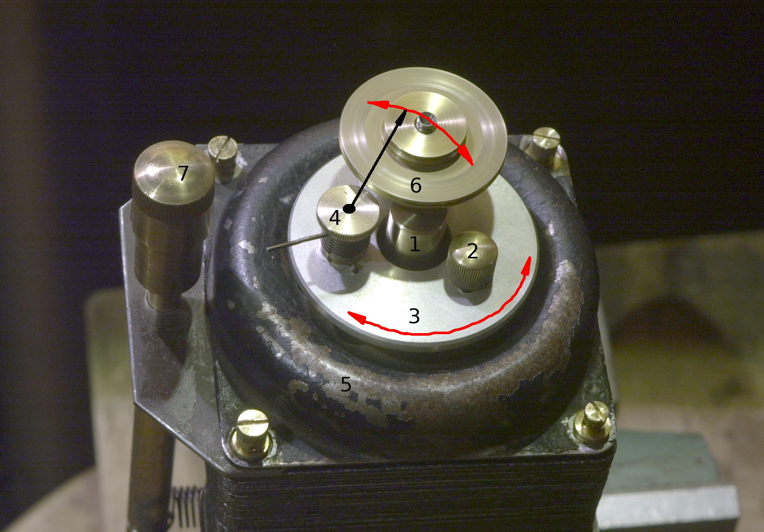
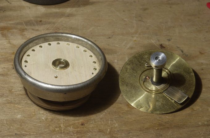
The lower base 8 (Fig. 14) is inserted into the hole in the engine cover and is attached from below with a locking ring 9 so that the assembly assembly rotates in a circle relative to the engine cover with some force. On the lower base 8, the upper base 3 is installed, which is attached with the help of the part 4 so that it rotates freely around the axis of the node 4 with a minimum gap between it and the lower base. With the help of a spiral spring, the unit 4 presses the pulley 6, which is fixed on the upper base to the drive shaft 1. The screw 2 is used to fix the upper base 8 in the position when the pulley 6 does not touch the drive shaft 1, which eliminates the deformation of the rubber coating of the pulley when the motor is turned off.
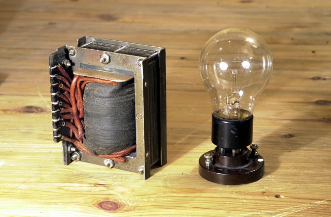
However, the problems did not end there - it soon became clear that the mechanical speed stabilizer does not accurately respond to changes in the mains voltage: there were audible detonations of the piano sound (the piano is the most sensitive instrument to detonations) appeared when the mains voltage changed by only 1.5 volts, and such changes occur constantly in any apartment. Apparently, an electronic stabilizer was needed, but a transistor AC stabilizer would negate all the advantages in the sound of this motor. The solution was found in the form of an archaic parallel stabilizer with a saturated choke, a shunt included where an incandescent lamp is used as a barretter. The exact formulas for calculating such a stabilizer could not be found, as a result, the shunt parameters were found experimentally - for an engine with a supply voltage of 150 volts and a current of 120 mA, it turned out that core with a cross section of 20×15 mm and 1100 turns of wire, with a diameter of 0.4 mm, was needed. As a quenching resistor - baretter, an incandescent lamp of 100 watts came up. The stabilization coefficient of such a node turned out to be only 3.2 (when the mains voltage changes by 10%, the output voltage changes by 3.2%), but this was enough to remove the problems of detonation during fluctuations in the mains voltage in the apartment. An unpleasant feature of such stabilizers is the increased hum of the choke core operating in saturation mode, in order to extinguish the vibrations, the choke had to be installed on a stack of felt 2 cm thick.
Despite all the efforts made, the problems with the uneven rotation of the engine have not completely disappeared, since 1) - old asynchronous motors with a thick shaft, a diameter of 8 mm (having an unreasonably large friction in the bearings) and a mechanical speed regulator are heated to 70 degrees. With warming up, the gaps increase and the viscosity of the lubricant decreases, respectively, the speed of rotation gradually increases. This could partially be solved by using liquid oil, but then you have to lubricate the bearings more often. 2) - during the operation of the drive, occasionally there were minor jumps in the speed of rotation, the probable reason is that some microscopic particles fall between the working surface of the brake and the brake disc of the stabilizer, or there is uneven wear of the brake. Leather and felt of different densities were used as brakes. It turned out that all of them work without problems only for a short time - a maximum of a few days and that they need to be soaked in oil, otherwise they make noise, whistle and quickly wear out. At the same time, as soon as the surface of the brake begins to get dirty, the above-mentioned speed jumps occur. These jumps are visible only on a strobe light with a diameter of 30 cm, that is, they are insignificant and almost invisible to the ear, but they are always there and it seems that there is no escape from them in such old engines. In general, the use of uncompromising sound, but technically imperfect engines is definitely not for the faint of heart.
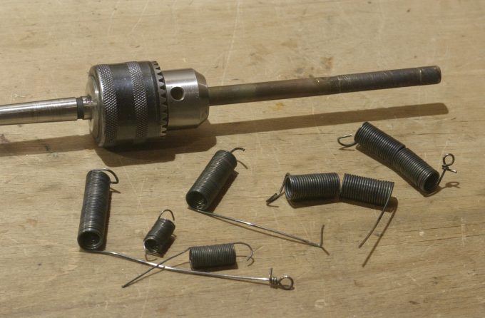
As in the Testing Audio System, the motor suspension springs are made of steel piano strings with a diameter of 1 mm, wound according to (see winding rules) on a thin-walled brass tube with a diameter of 10 mm, for the convenience of winding, the tube is inserted into the drill chuck (Fif. 20). The winding is made over the burning gas, the wire on the bent section should be red-hot, in this case the spring will be smooth and with tightly fitting coils. The finished spring is quenched in cold water, it is necessary to lower it sharply and keep the spring vertically, the beginning of the spring should be at the bottom. Then, on both sides of the spring, 2-3 turns of the overheated wire have to be removed, after which the ends of the wire can be bent without fear that the wire will crack.
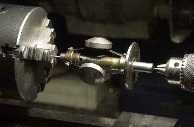
For engines with mechanical speed stabilization, the stabilizer assembly must be carefully balanced. To do this, the stabilizer together with the rotor must be fixed horizontally on the needles that rest against the technological, centering holes of the rotor axis (Fig. 19), balancing is performed with special adjusting screws of the mechanism.
Disk
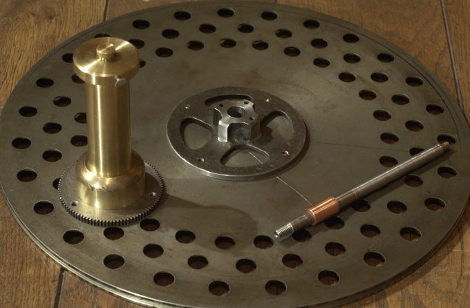
As a base, a cast disc from a Phonograph of the 1910s was used. All parts of the assembly are connected so that their axial projection of the < em>vectors is directed from the bottom up.
Tonearm and cartridge
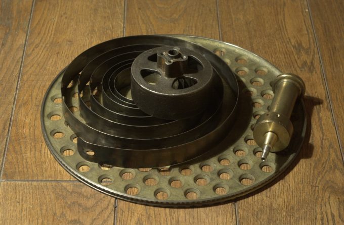
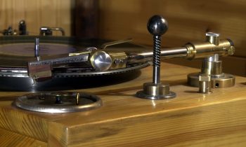
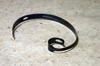
The system uses a modified clock spring tonearm, in which several parts were made anew to further reduce vector losses. From a technical point of view, the spring was modified (Fig. 26). The classical clock spring has a non-linear resistance section only at the very beginning of its twisting, until the first turn is completely wound on the drive shaft. With further twisting of the multi-turn spring, there is a long section of almost linear spring resistance, this feature is used in watches, where constant traction is important during operation. In the tonearm, only a non-linear section is used thus the needle pressing force will be different for thin and thick plates, as well as for curved records at depressions and elevations. This point is a technical disadvantage of any spring tonearm in comparison with the balanced version. In a spring tonearm, it is desirable to have a section of approximately 5 mm of vertical movement with a minimum change in the weight of the tonearm. For the sake of greater linearity of this section, it was decided to make a spring with a variable width - at the beginning (at the drive shaft), the spring was narrowed more than twice, its native thickness began only after one and a half turns, so that as a result, the nonlinear section of the spring resistance stretched from one turn to two and a half turns, and the upgrade as a whole reduced the fluctuations in the clamping force by about two times.
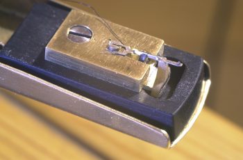
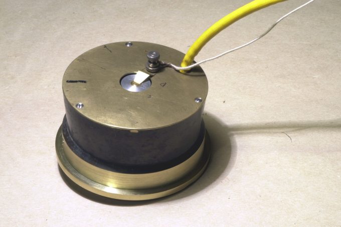
The cartridge uses a homemade crystal. Unlike the previous version, where the conductive surfaces were covered with graphite-shellac varnish, in this version, strips of thin aluminum foil, taken from an old capacitor, are glued to the crystal. Garlic juice is used as the glue. The capacity of this version was one and a half to two times higher, ceteris paribus, which made it possible to use thicker, mechanically more reliable crystal plates.
Switches and connectors
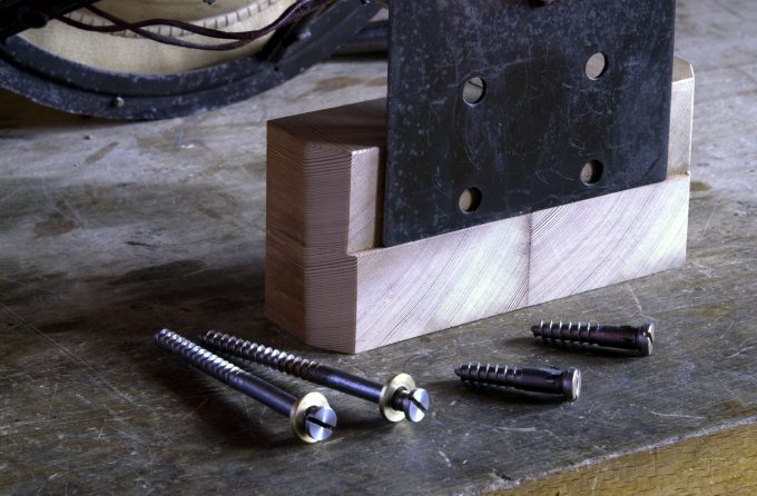
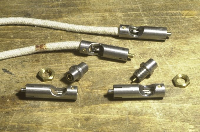
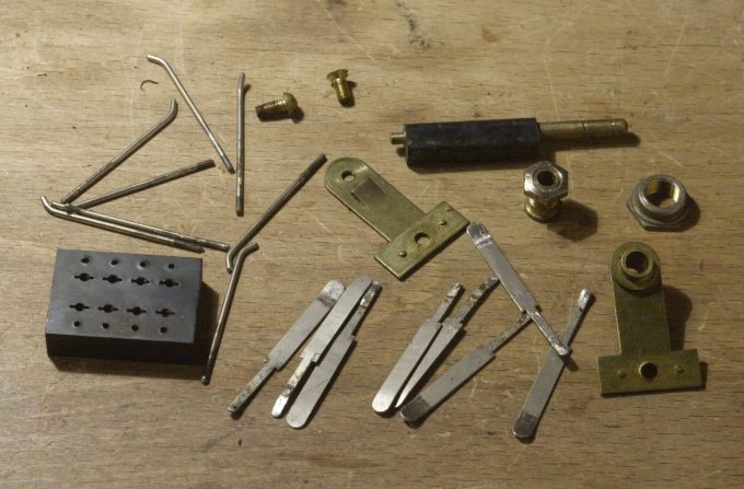
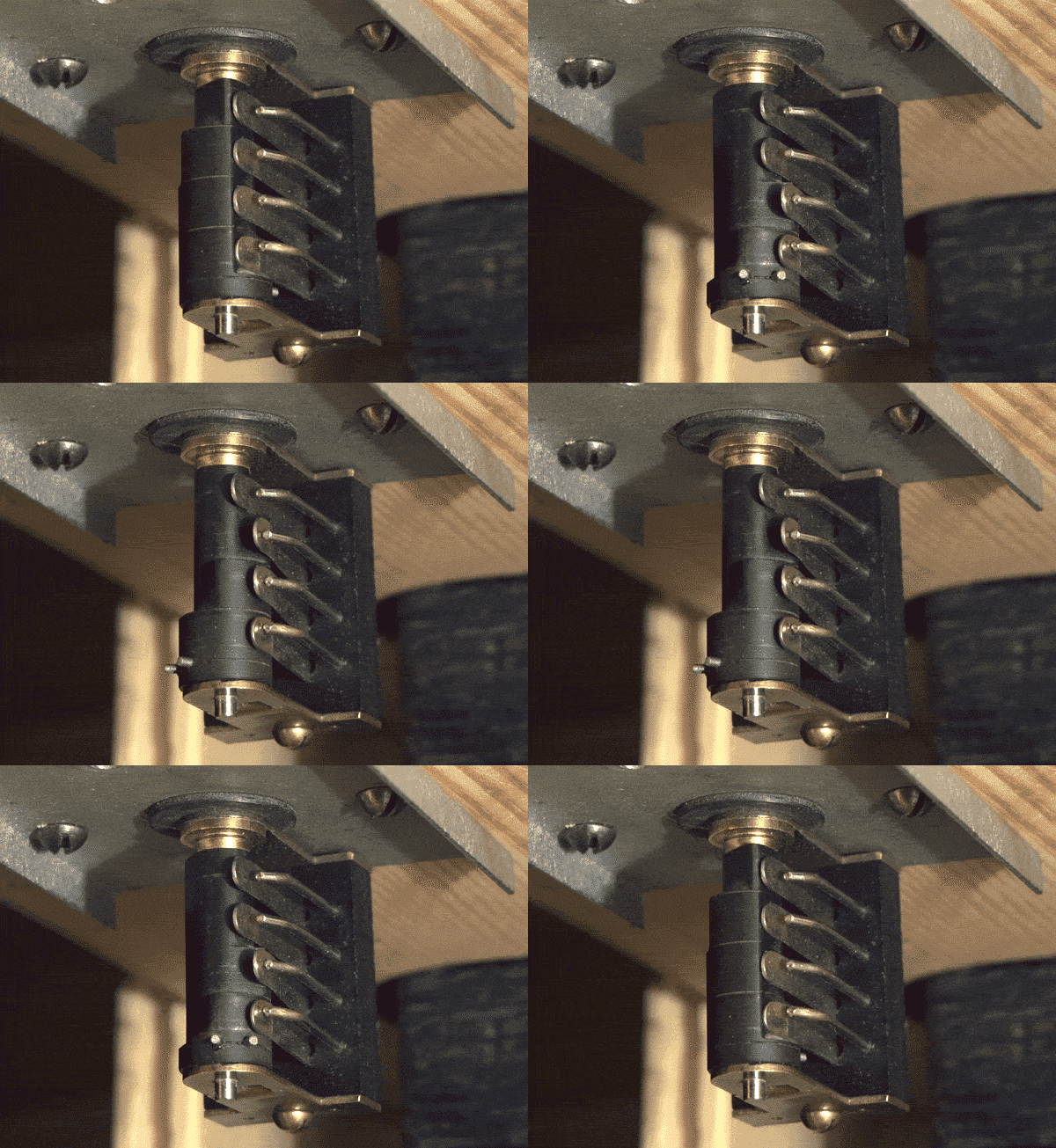
All switches and connectors were self-made of metals of venerable age and assembled taking into account their orientation. The 4-position switch (Fig. 30) allows you to turn on the mains voltage, the anode voltage, the drive motor, and the strobe lamp in series. The rest of the switches were also composed from the details of the 1920s or assembled from scratch so that the overall vector of each part co-oriented as much as possible with the direction of the vector of the cabinet at the attachment point of the part.
Potentiometers
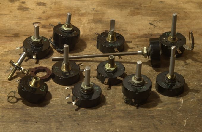
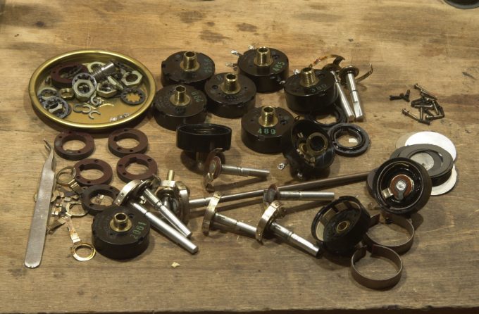
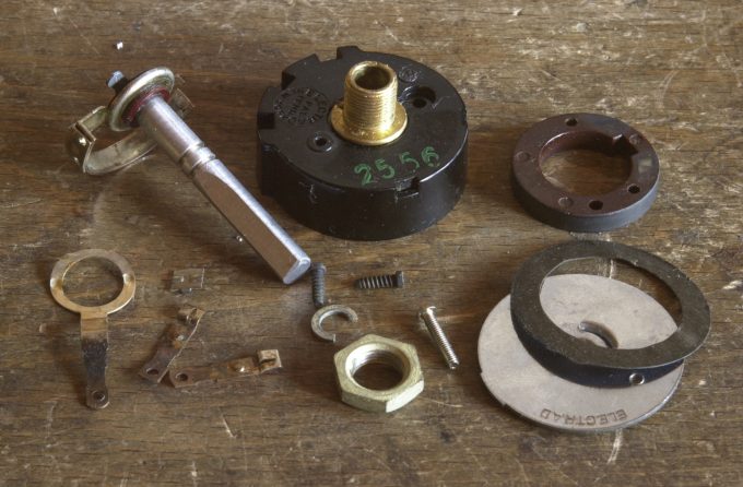
Potentiometers are made from suitable parts from several identical factory copies. For an example of working on resistor parts, see Vector-phantom.
Transformers
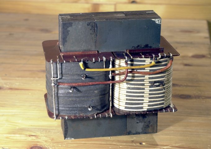
Special handmade power transformer was used (see Symmetric transformer for push-pull amplifiers and full-wave rectifiers). The cross section of the core is 38×38 mm, the mains winding is 1140 V, the anode power winding is 1160 turns, the four filament windings were located outside and were not insulated so that it was possible to obtain different heater voltage by soldering directly to the turns. In the secondary coil (which is not connected to mains socket), the number of turns in all windings was increased by 5%.
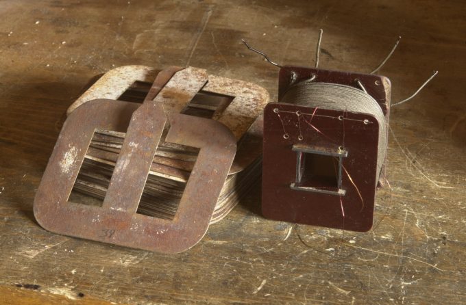
All other transformers and chokes are single ended, they use conventional three-legged magnetic cores from old tube radios. The iron of the magnetic cores is laid in such a way that the total vector of the magnetic cores is co-directed with the chassis. The chassis, in turn, is co-directed to the part of the cabinet on which it is installed.
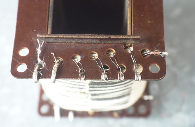
The transformers has no additional metal terminals. The wires themselves are used for this purpose, they just threaded several times through the holes in the cheeks of the frames. Such terminals sound perfectly clear if the direction of the wires and the transverse projection of the vector of the cheeks in the holes coincide. For example, if the direction of the cheek is from top to bottom, then the end of the wire must be threaded through the hole from above. Thus, if you need to bring out the tap of the transformer winding, then the end of the winding is threaded into the hole from above, and the beginning of the next winding is from below (Fig. 35), as a result, a co-directional "coil" is formed from the two wires at the edge of the cheek. The output of the external wire must be soldered to such a tap from below, the input, respectively, from above, then the entire node will be co-directional and will have almost zero vector losses.
Wirewound capacitors and volume control
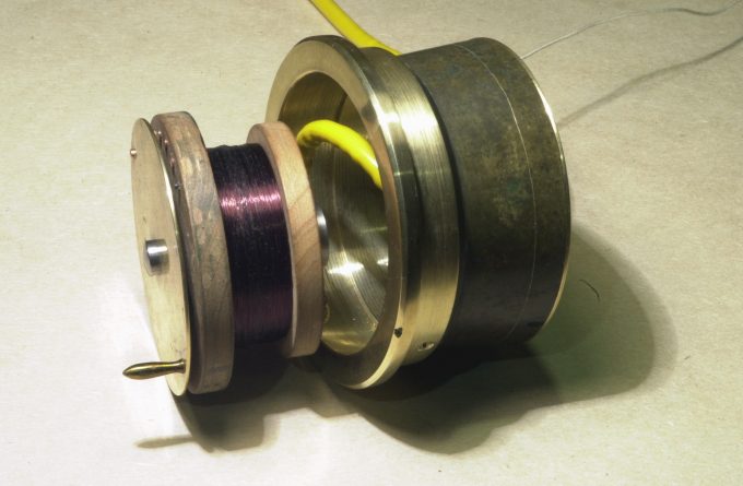
Variable wirewound capacitor is used to adjust the volume when listening to records using a piezoelectric pickup and/or as a variable capacitor in the frequency response correction circuit of the preamp. The coils are wound with a 0.1 mm wire on a common wooden frame with a diameter of 37 mm, winding starts from the least coil. It is almost impossible to calculate the capacitance of coils wound on the same frame, since after winding each subsequent coil, the capacitance of the previous one increases due to contact with the earth conductor of the neighboring coil. The gap between the wires is also redused due to compression of the inner layers by external ones. The experimental data are summarized in a table.
| Capacity, nF | 0.36 | 0.59 | 0.91 | 1.25 | 1.8 | 2.87 | 3.9 | 5.3 | 7.4 | 10 | 16 |
|---|---|---|---|---|---|---|---|---|---|---|---|
| Turns | 10 | 15 | 25 | 40 | 60 | 95 | 145 | 230 | 350 | 540 | 850 |
In practice, the location of the wirewound regulator relative to the mains transformer was unsuccessful, with a minimum volume the 100 Hz hum from the transformer was heard. The hum was reduced to an acceptable level by installing a steel plate at the bottom of the regulator. To completely eliminate possible interference, such a regulator, like any small-signal audio transformer, must be made in a steel case.
Scheme
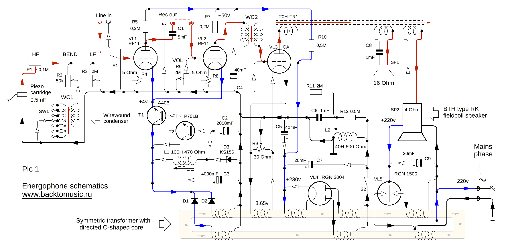
In the input stage of the amplifier, two RE-11 tubes with a tungsten direct heater were used. In fact, the entire amplifier was created for the use of these old 1923 tubes in it. The lamps have an unusually clear, melodic voice, although their parts, like those of all other tubes, are randomly connected in terms of directivity and it is desirable to choose from several ones. The main problem with using RE-11s is the low gain and the need to use stabilized constant voltage for heaters - all other options give an unacceptably high hum. Any voltage stabilizer in tube amp is definitely a bad idea, the sound from its use loses a lot. But in comparison with indirect tubes with an oxidized cathode, tungsten RE-11 win by a large margin and if you correctly implement the scheme of the simplest stabilizer, you can steel keep their potential at a very high level. The stabilizer has two soviet transistors A406 and P701B of the 1960s, a zener diode KS156, a choke and two electrolytic capacitors. All components were carefully selected for maximum clarity of theirs sound.
Before the first stage, there are piezo cartridge signal correction circuits-the RC circuit (R2, WC1) allows you to regulate the high and mid frequency level and change the inflection point of the frequency response to the HF. R1 changes the HF level, R3 allows you to adjust the low frequency level. The input switch "line in-LP" is installed at the input of the first stage. From the anode of the first lamp, an output is made for digitizing records. The volume control is extremely simplified, but it works without complaints, since the RE-11 plays on small signals without distortion, even with 10 volts on the anode. The second stage is similar to the first, but since the resistance of the next stage is large, a wire capacitor WC2 10nf is installed at its output. The output stage works according to the usual negative bias circuit by means of a choke, which allows the use of capacitors of a smaller capacity than in the case of fixed or automatic bias. The power supply rectifier of the amplifier is standard.
The speaker power rectifier uses a cold cathode rectifier RGN 1500. Due to the lack of heater, ceteris paribus, it sounds clearer than conventional rectifiers, but it can give interference in the form of a crackle (harmonics of 50 Hz) so the input circuits need to be shielded more carefully.
Installation
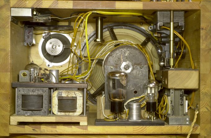
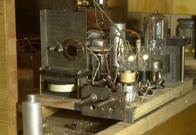
The installation turned out to be too close, the distance between chains with small signals and the mains transformer should be larger, but after some shielding the hum was fully eliminated. On Fig. 40 on the left are a choke and output transformer mounted on the chassis, there are two rectifiers at the center, on the right you can see engine rotation stabilizer choke and the motor itself above it. On the right inside is a mains transformer. The mains transformer, engine choke and the lower part of the motor are mounted on the felt cushions. The co-directed mounting wires are tied into harnesses. Fig. 41 shows the chassis, the choke L1 at the left, above it the cooler of the transistor T1 A-406. On the right is the RE-11 input tube with removed shield, followed by the second RE-11 and the CA power tube. In Fig. 42 on the left at the bottom is the line-in entrance, the input switch S1 is above it, behind it a four-position switch of mains supply, anode voltage delay, motor on and the LED strobe illumination on. At the bottom right are volume R6 and LF correction R3 potentiometers. Nearby there is an ancient voltmeter of the early twentieth century, which was dusted in my pantry for fifteen years, I do not know why I installed it there, it does carry no semantic load.
Sound
If we consider the whole system only as an active loudspeaker, then due to the "extra" details of the recordplayer, it turned out to be incomparably more complicated thanEnergy Horn. At the same time, the most influential component of the system - the British Thomson-Huston speaker was definitely preferable in its potential to that of the EH. The BTH had an incredible ease in midbass, fine clarity and overall warmth of the 1920s, but vectors of its components, even after a thorough reworking was not to be as precise co-oriented as it wanted. When I first installed the BTH in the case, it had annoying hard notes in the sound. I could not get close to the sound of EH in terms of purity and transparency for a long time: I reworked and refined parts of the mechanics, changed the wiring, and so on and so forth. In the end, the sound was opened up enough to finally feel the long-awaited satisfaction - thanks to the details of the 1920s and the most accurate possible Vector orientation of the details, the project in comparison with the EH was a good step forward.
The piezo cartridge was redesigned to expand its frequency range, while maintaining the original clarity and subtlety of the narrower frequency band. Most of the tracks opened up and began to sound more expressive, in some cases after compression and copying to the site the gain was not so noticeable. To demonstrate the sound of the cartridge, several records were re-recorded with it. Examples of new digitizations are shown below.
You can listen to other examples in the Music section .

